Update!
So I ran into some interesting issues over the past week. I wanted to share some of them with you guys as I’m going.
Board Quiescent Current
When I first went over the quiescent current measurements, I was pleased with the results. I went to revisit on some of the newer boards I have here and something was wrong. I was getting anywhere between 10-120uA which is not great!
It’s difficult to isolate the exact cause with a fully assembled board so I built a one-side board for nPM1300 validation.

While their power supply chip does seem fairly robust, it seems there are some bugs around the usage of I2C. I was able to play with it more last night and got about 1uA which includes the Iq for the nPM1300 with one buck running along with the LIS2DH12 in deep sleep (typical 0.5uA)
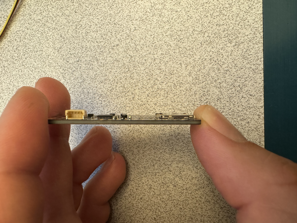
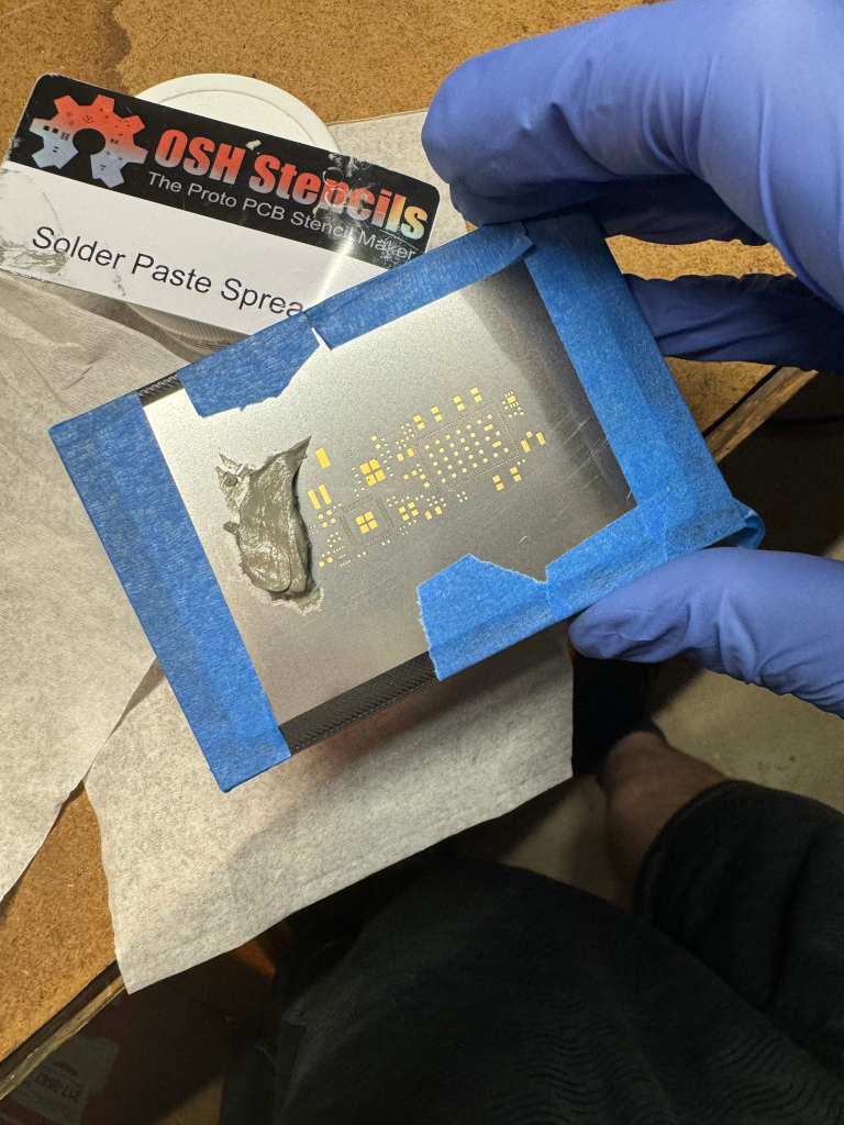
I’m going to build another one today to confirm I can get the same results. Then attempt to assemble the other side. Assembling the module is tricky especially when hand applying solder paste. I threw together some jigs to make that process easier.

I do need to adjust this guy a bit to raise the PCB higher. Also will be adding some mounting holes so I can put one on the bed of the pick and place.
En pin operation
I was able to validate the EN pin which is hooked up to the SHPHLD pin on the nPM1300. This allows you to completely sleep the device and wake it up by pulling EN to ground for 96ms or plugging in USB. It was < 400nA which was great.
Other open items
- Get the board as low current as possible. More on this today.
- I have seen one issue so far when “recovering” the device when switching off buck2 for power saving purposes. This keeps the RP2040 powered off so it can be used to program the nRF9161. Usually you can hold the RST button and program (default power on is with both buck converters). This prevents the nRF9161, if programmed to do so, from turning off buck 2 which powers the RP2040.
- Confirm the new QWIIC works as expected